
So the value of hold doesn’t change until the next sample. In ADC, HOLD is the second block and it doesn’t have any function because it simply holds the sample amplitude till the next sample is taken.

The process of ADC can be done like the following. The block diagram of ADC is shown below which includes sample, hold, quantize, and encoder. Classification of ADCs based on factors like performance, bit rates, power, cost, etc. Dynamic characteristics of the high-performance ADCs are improved measurement repeatability, low power consumption, precise throughput, high linearity, excellent Signal-to-Noise Ratio (SNR), and so on.Ī variety of applications of the ADCs are measurement and control systems, industrial instrumentation, communication systems, and all other sensory-based systems. With the invention of a wide variety of ADC integrated circuits (IC’s), data acquisition from various sensors becomes more accurate and faster. One of the major benefits of ADC converter is the high data acquisition rate even at multiplexed inputs. Bit resolution is nothing but how much accuracy can an analog to digital converter can convert the signal from analog to digital.The sample rate of an ADC is nothing but how fast an ADC can convert the signal from analog to digital.Typical applications of A/D converters include microprocessor interfacing, data printing and recording, digital voltmeters, and control of LED or LCD displays. Conversion time is the time required to convert an analog input into valid digital outputs. Another important parameter for A/D is conversion time. Similar to DIGITAL TO ANALOG CONVERTER, specifications such as resolution or nonlinearity are also used for A/D converters. It is a complete D/A converter that can be configured as an A/D converter by using an external comparator and a quad two-input Schmitt trigger NAND gate. Datel’s ADC-MC8B is an 8-bit monolithic multi-function A/D-D/A converter that operates on a single +5-V supply. It has a six analog-input voltage range with parallel or serial outputs and requires no calibration. It is capable of 8-bit resolution in only 600 nano seconds. Datel Intersil’s hybrid ADC-815MC is a very high speed 8-bit successive-approximation A/D converter. Teledyne 8703 8-Bit CMOS Analog-to-Digital ConverterĪs in the case of monolithics, there are many hybrid A/D converters, such as the successive-approximation A/D with input buffer amplifier, the low-power CMOS A/D, the fast A/D with sample-and-hold, and the ultrafast A/D with input buffer amplifier.

The circuit diagram of a Teledyne 8703 8-bit Monolithic CMOS analog to digital converter is given below. It has an infinite input range since any positive voltage can be applied through a scaling register R in. It has all the needed active elements, and has latched parallel binary outputs with strobed or free-running conversion.
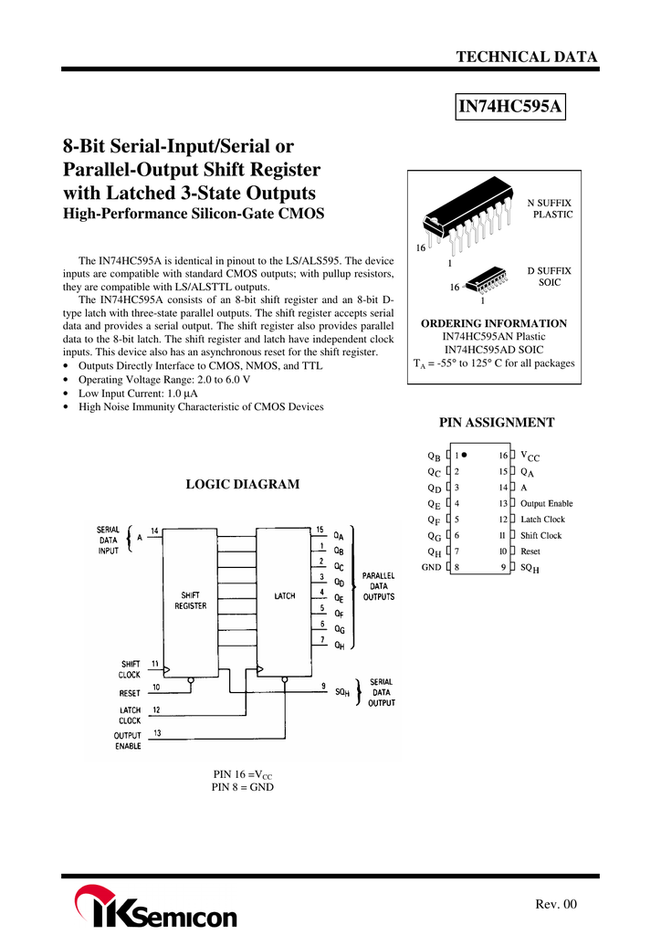
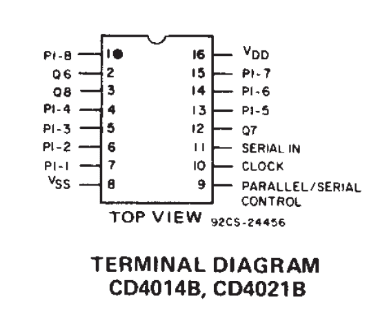
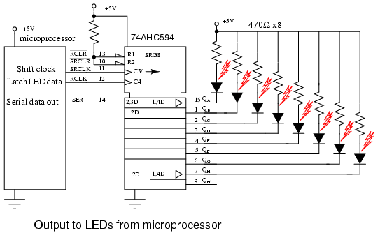
#8 bit parallel to serial converter circuit diagram full
The converter is made compatible with a microprocessor and it also exhibits high stability over a full temperature range. The figure below illustrates an 8-bit monolithic CMOS analog to digital converter with three-state output. In addition to this, the outputs of A/D are coded in straight binary, binary-coded decimal (BCD), complementary binary (l’s or 2’s), sign-magnitude binary, and so on. Apart from it, there are also many types of monolithic analog to digital converters, such as the integrating A/D, integrating A/D with three-stage outputs, and the tracking A/D with latched outputs. The basic ANALOG TO DIGITAL (A/D) CONVERTER CIRCUIT has already been explained in an earlier post.


 0 kommentar(er)
